
In the menu item "CUBEVISIONEDITOR" you can create or edit projects.
Open CUBEVISION Editor application.
-
Open the "CUBEVISIONEDITOR" via the web interface.
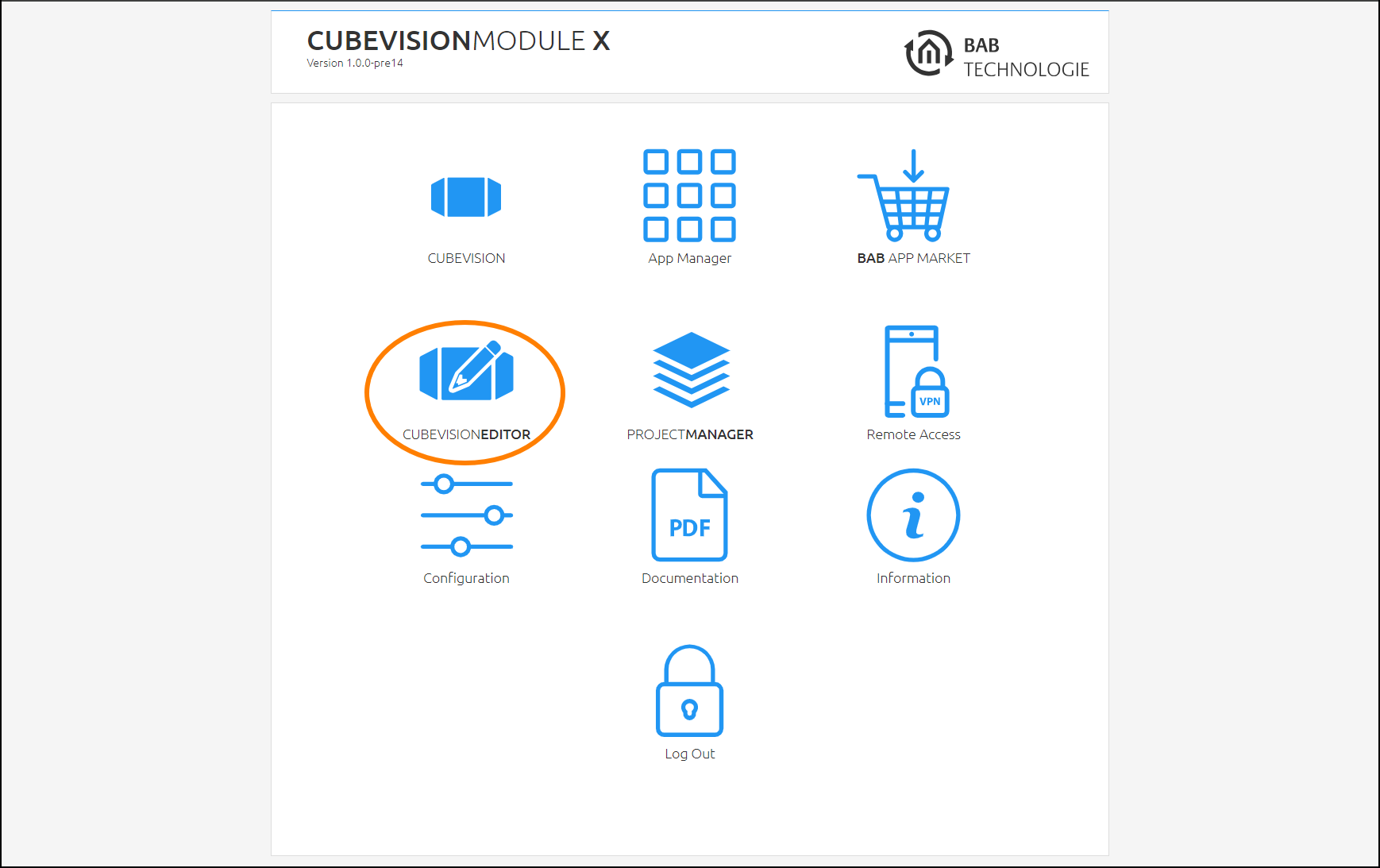
-
In the open editor, new projects can be created or existing projects can be edited.
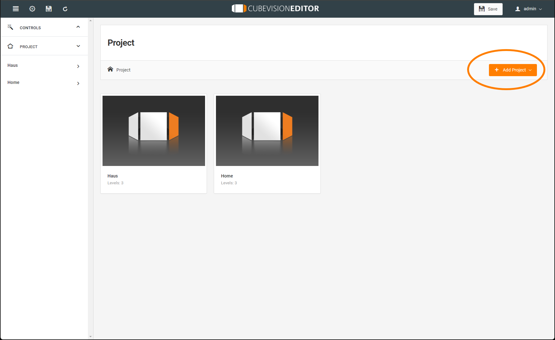
The CUBEVISIONEDITOR start window opens with an overview of the projects already contained.
CUBEVISION EDITOR general
The menu bar of the CUBEVISION EDITOR
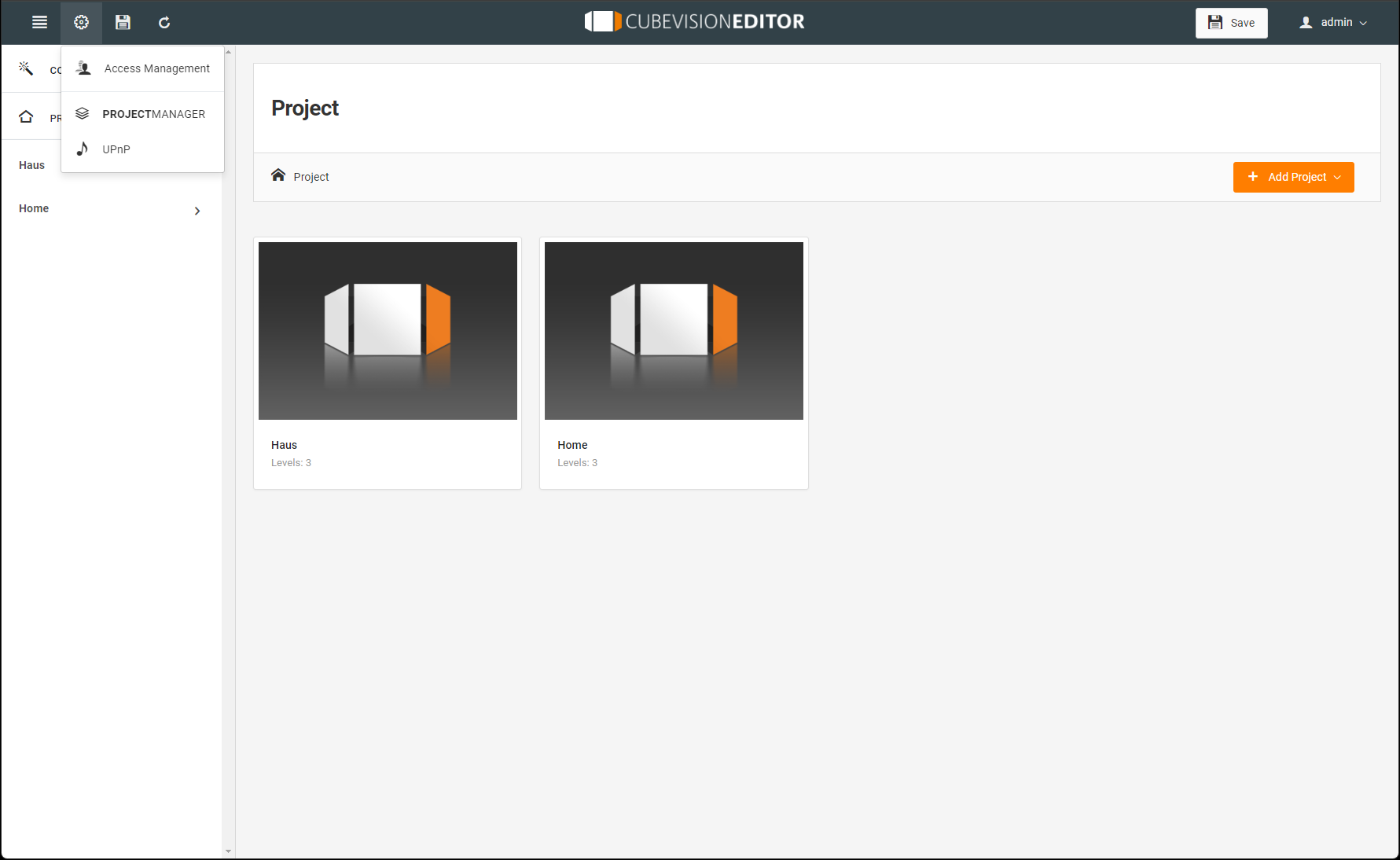
Header functions
-
Gear icon.
-
Access management: Configuration of access rights for Visu users created in PROJECTMANAGER
-
PPROJECTMANAGER: direct page jump
-
UPnP: Creation, management and configuration of UPnP devices
-
-
Title (centered). Calling up the start window
-
Floppy disk symbol. Save visualization data
-
User symbol. Log out.
Project administration for CUBEVISION EDITOR
New projects can be created directly from scratch or the creation is based on a data import through a corresponding KNX project file.
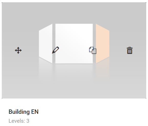
To edit, duplicate or delete the project, go to the image icon of the respective project and activate the desired function.
Here you can also move the projects into a new arrangement.
CUBEVISION EDITOR Configuration
The CUBEVISION visualisation is configured in the main window of the CUBEVISIONEDITOR. To create a CUBEVISION visualisation, a project is existing, or a project must be created in the first step.
Projects
To create a new project, open the menu item "+ Add project". The following options are available:
-
The new project can be created completely,
-
based on "From project database (ETS terminal)",
-
with the help of an "Import (PROJECTMANAGER)".
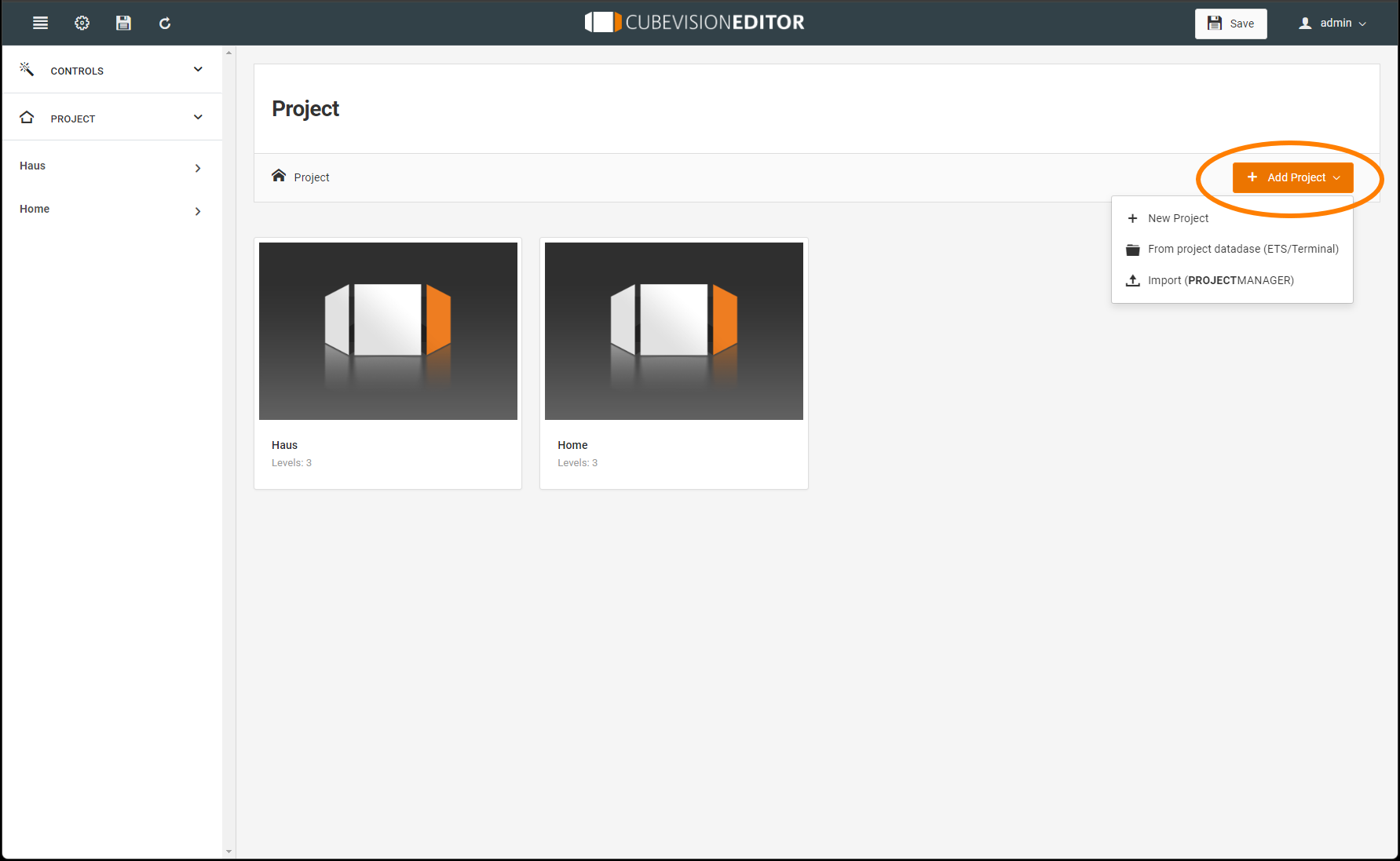
This creates a new CUBVISION project file and a new ICON for the new project is created on the screen.
On the left side of the display, the entire structure of the project is shown and displayed in a tree structure. You can use this structure to access each displayed stage of the project for editing.
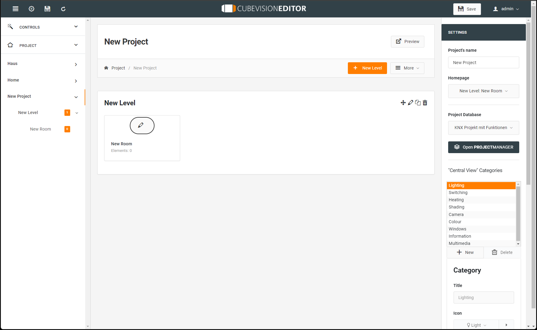
After the project has been created, the project can be edited. This includes editing the settings for the project:
-
Name of the project
-
Start page when opening the project,
-
Assignment to a project database
-
Creating and editing the categories for the "Central View"
-
But also information for diagrams that are used in the visualization.
If you do not yet have this information, you can return to this area at any time to continue editing.
After the project has been created, it can be edited.
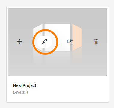
Move the mouse to the icon of the project and the menu appears with:
-
Move icon,
-
Edit project,
-
copy project,
-
and delete.
Activate Edit to enter the building structure.
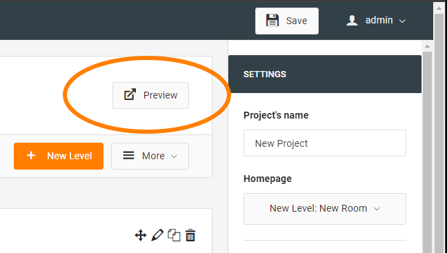
When editing the project, you have the option of viewing and checking your settings and changes in the CUBEVISION visualization in an active preview.
Project (Building)
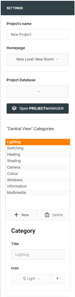
The settings for the project can be edited on the right side:
Project’s name: Assign a name for the project or the building here.
Homepage: Define here the start page that is displayed when opening the visualisation or the page for the return, if such a function has been activated, in case of inactivity.
Project database: If a project database already exists, which has been imported for example, you can select the project database here.
"Central View" Categories: Manage the categories for the "Central View" here. Additional categories can be created for the prepared categories, which are displayed in the visualisation with a selected icon. Categories that are not needed can also be deleted in the administration.
Please note that the existing standard categories for the "Central-View" cannot be changed or deleted!
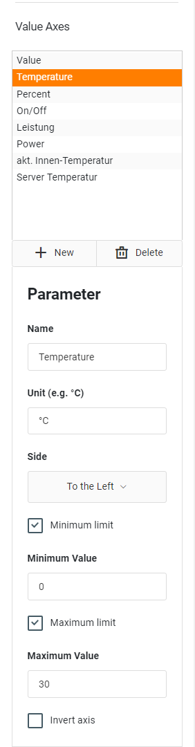
For the use of diagrams in the project, further basic settings can be made here in the "Settings" menu:
Value Axes: If the standard selection for a value designation is not sufficient, further value designations can be added via "+":
Parameter
Name: e.g. Value for energy consumption.
Unit: Assign the corresponding unit to these values, e.g. °C.
Side: Is the position in the diagram where the information about the value should be placed; left of right.
Minimum Limit, Maximum Limit: Activate these fields if you want to set up corresponding intervals. When activating the function, an input field is opened.
Invert Axis: Activate this field, if necessary, e.g. in energy grids the energy yield of a PV system is displayed as a negative value (energy return flow or feed-in). In the graphical representation, however, the yield should be shown as a positive graph.
Level (Floor)
After the basic configuration of the building has been carried out, the structure continues with levels and rooms.
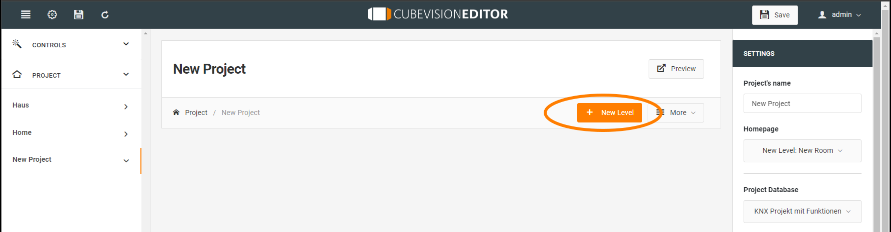
A name and an abbreviation are assigned to the created level via the settings. The abbreviation serves as a short name for the visualisation.
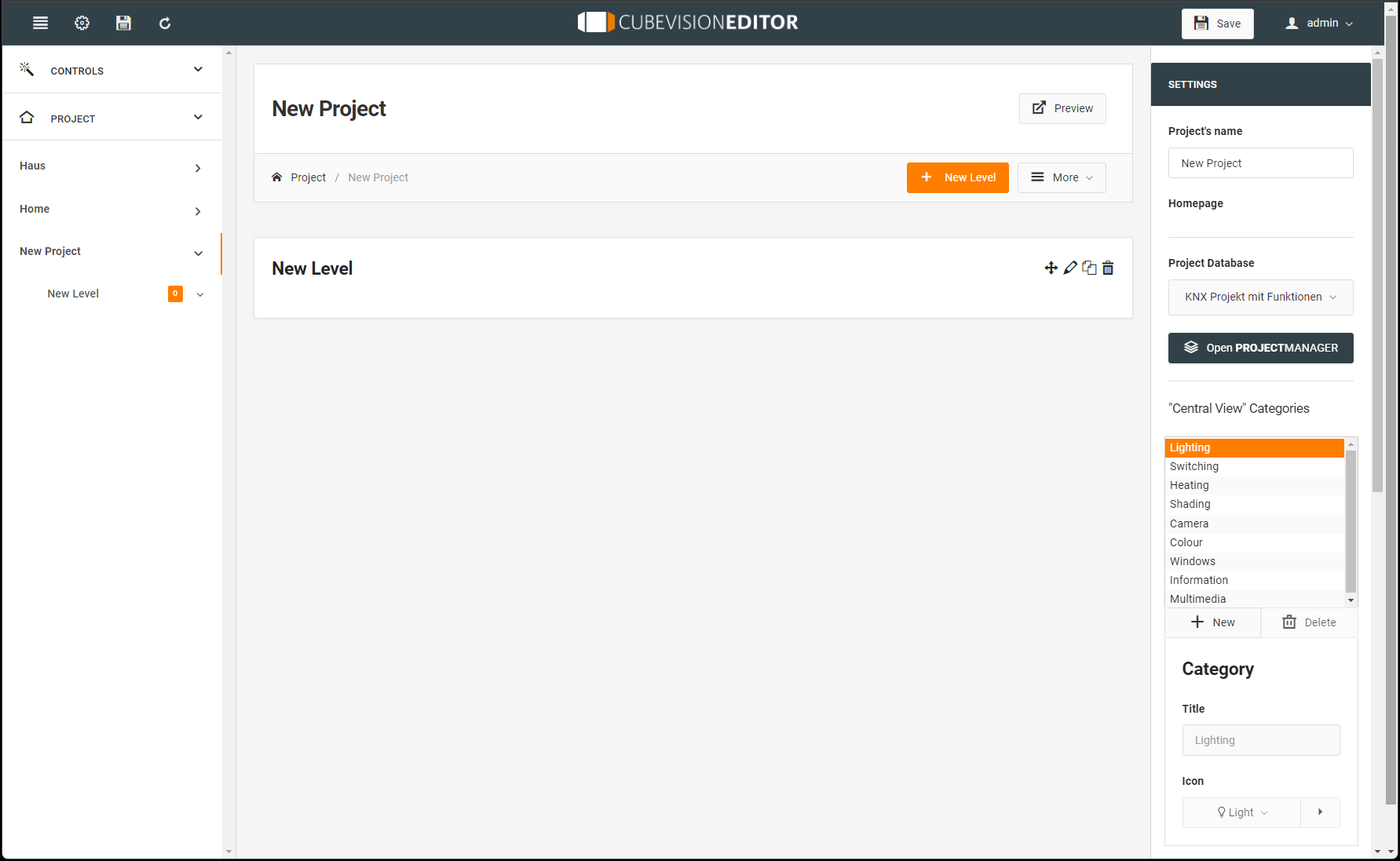
Room
In a similar way as a level is created, the rooms are created in the levels. There are various ways to create a room.
-
Via the symbol "+" or
-
If a room has already been created automatically, you only need to click on the edit symbol.
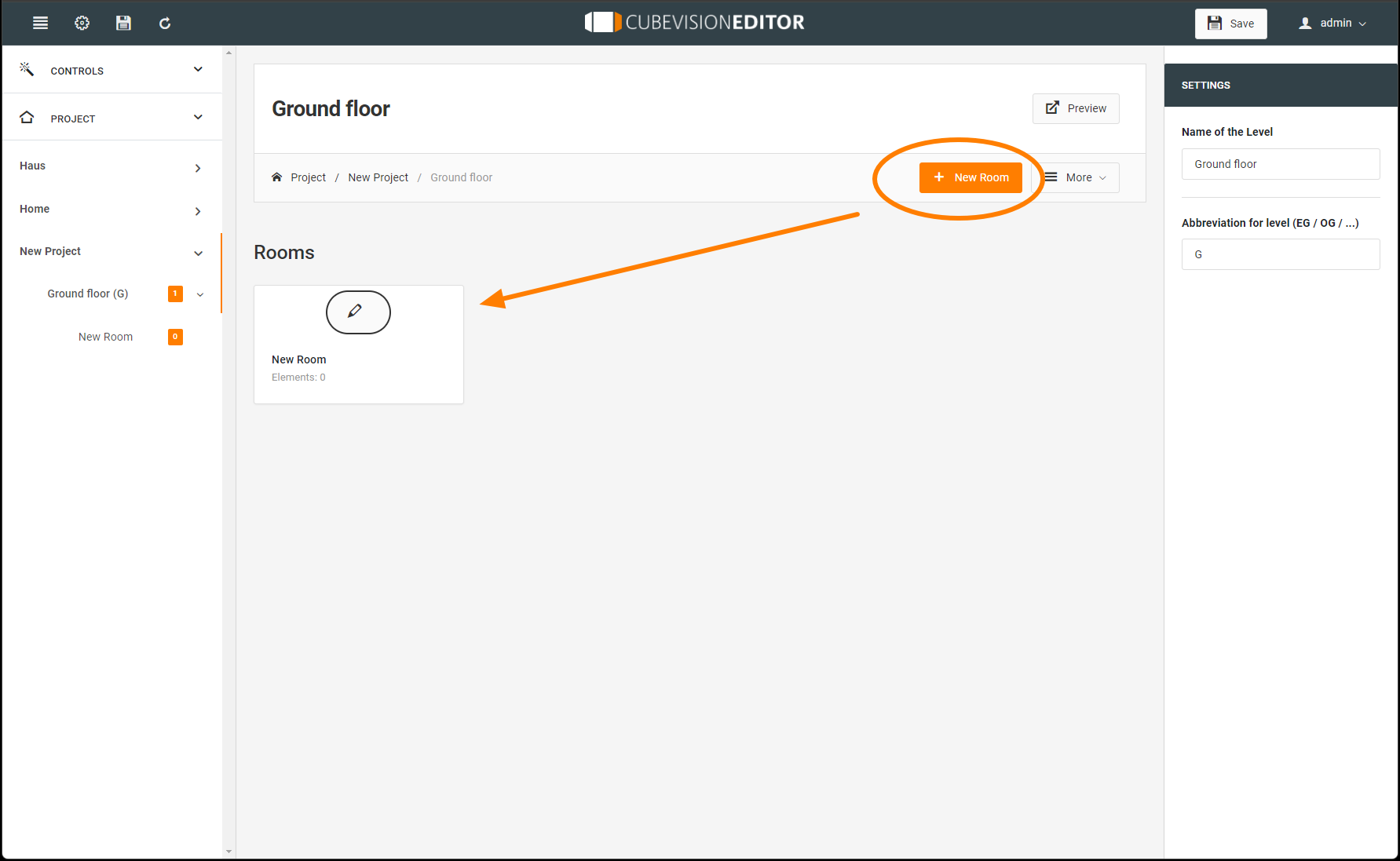
A name, an icon and a background image are assigned to the created room via the settings.
Via the additional menu "=More" it is possible to duplicate or delete an area in the current structure.
-20240424-222856.png?cb=5a712a8e5f7e248584fe4d99fee8d957)
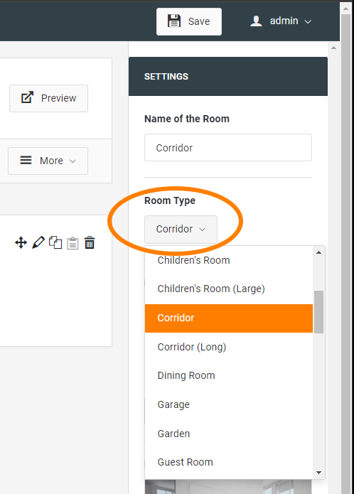
Room-Type
The room type is selected via the highlighted drop-down list.
This selection automatically sets a corresponding room icon and background image.
If there is no suitable room type in the list, the room icon and background image can be selected individually.
Room Icon
Room icon: The room icon can be selected via the pull-down menu or the extension symbol opens a submenu for editing the icons. Here you can also import your own icons and assign them to your visualisation.
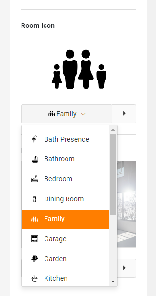
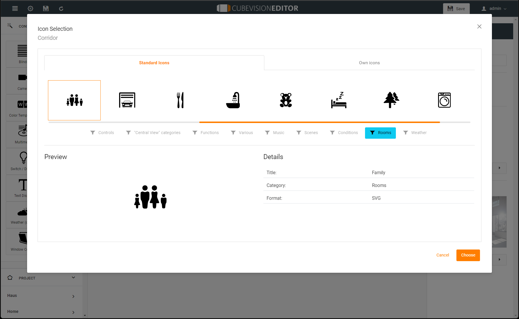
The selection of the room icons determines the symbol that is displayed in front of the room name in the room navigation in the CUBEVISION Phone view.
In this way, the icons are used for a quick and convenient entry for operating the rooms.
Background Image
Background image: A background image is assigned to each room. It fills an entire side area (which represents a room) of the CUBEVISION cube. This picture is also shown in the Quick Navigation together with the name. The background image for the can be selected via the pull-down menu or via the extension icon opens a submenu for image management. Here you can edit your images, import images and make your selection as the background image for the room.
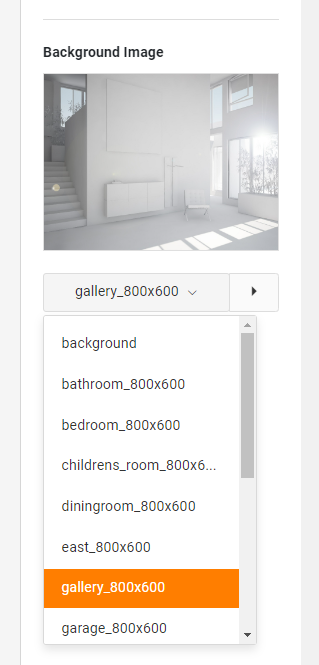
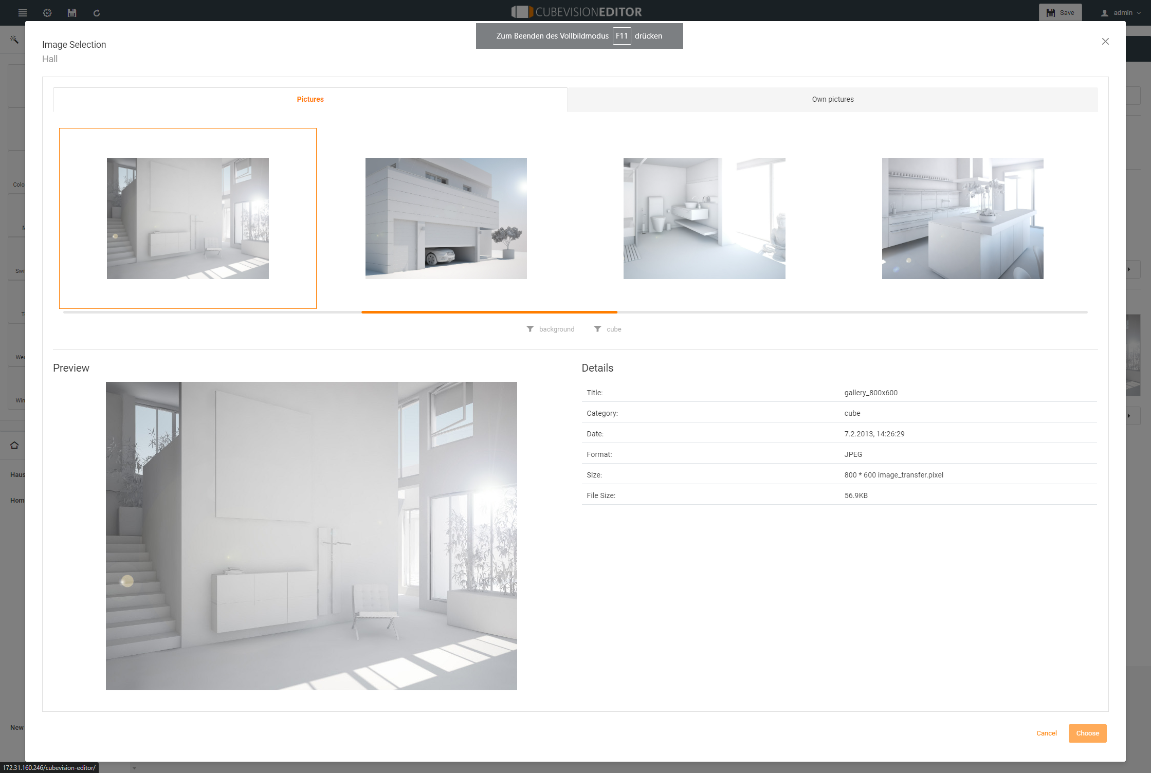
The recommended resolution for the background image of the room depends on the size of the end device on which the visualisation is to be displayed.
In principle, the resolution should be higher for larger end devices (PCs, 21 inch touch panel PCs) than for smaller end devices (smartphones or tablets).
If the background images are all very high-resolution, there will be no problems with large screens, but this may increase the waiting time somewhat on small devices.
Not only because of higher loading times, storage space should be used sensibly and the image size should be adapted to the end devices.
Room structure / Column Break
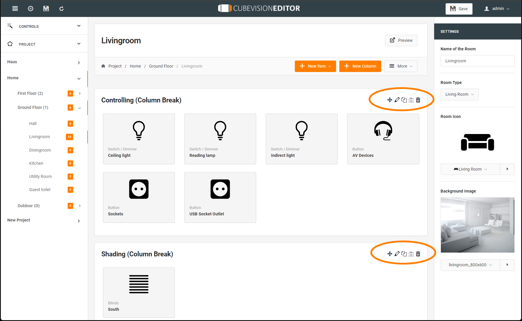
The operating structure within a room is particularly determined by the column structure. In this way, the control elements with configured functions within a room can be structured sensibly and clearly according to topics and habits.
The figures below show how the column structure is displayed in the Tablet and Phone view for the CUBEVISION visualisation. The columns should be named in such a way that the content of the columns is clear. In the Phone view, the columns can be expanded and collapsed, so the column designation is particularly important for orientation during operation.
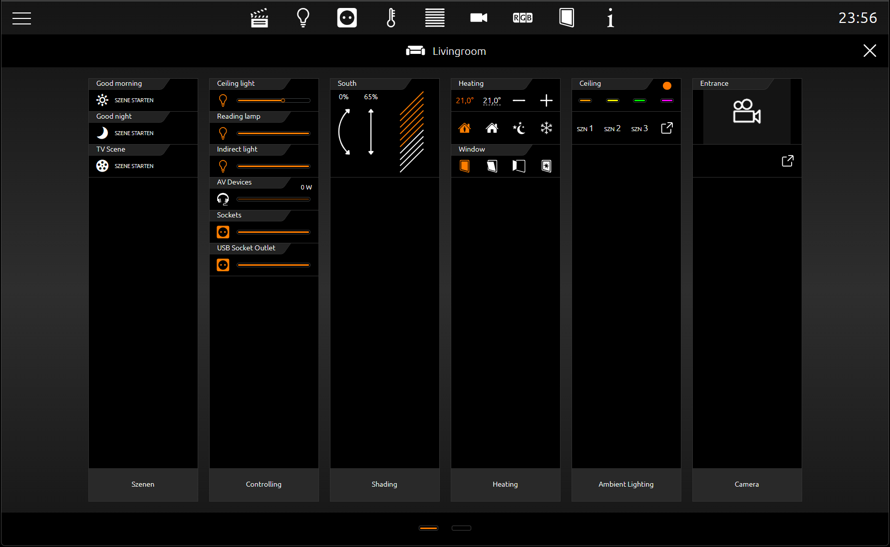
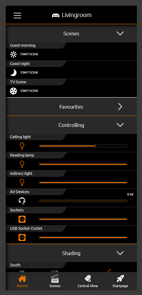
In principle, the number of controls elements is unlimited. In the phone view, the column area simply becomes very long. In the tablet view, depending on the height of the screen, the column is only divided until all controls are divided.
The representation of the CUBEVISION visualisation is based on the created spatial structure of the CUBEVISIONEDITOR. This structure can be changed quite easily with the following tools:
You have the following tools for this (following illustration, marked in orange):
-
With the first control icon the columns and elements can be easily moved.
-
With the editor pen icon the column name can be changed
-
The copy symbol can be used to duplicate an entire column.
-
Deleting rooms and columns by the icon
///