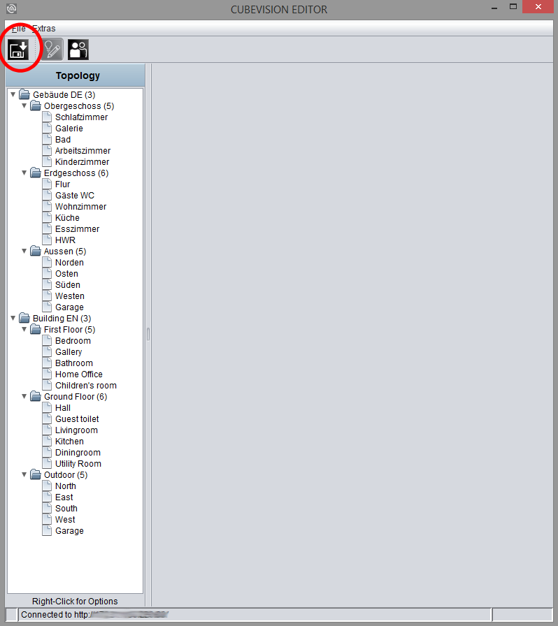
In order to configure the CUBEVISION visualization the CUBEVISION Editor is been used.
Explanation
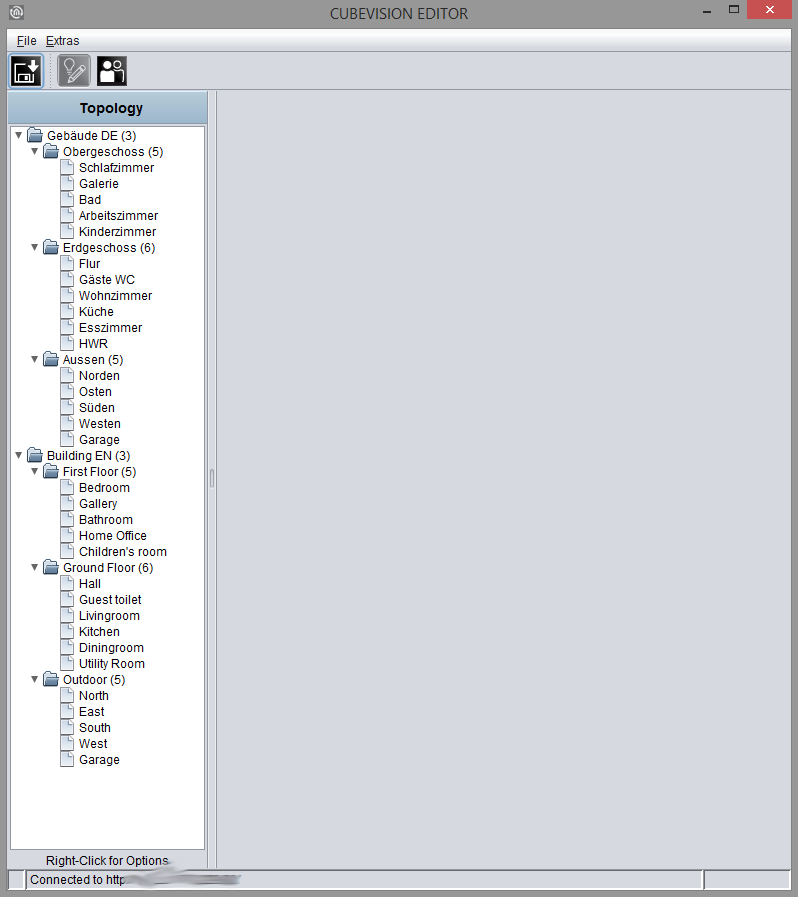
CUBEVISION Editor is divided in two areas. The left side shows the topology of the building. The topology is similar to a directory structure, as you can see in figure above.
As „building“, we describe a complete structure, which consists of floors (levels), rooms and elements. This structure will be described in form of a directory tree. This means that a directory depicts a level and a file presents a room. The elements (like switch, dimmer, jalousie, RTR, ...) will be added to the room in the form of a list.
The right half is reserved for configuration. That can be the configuration of a building, of a level, of a room and of operating elements. To call up respective configuration of these components, it would be enough to select them simply. Depending on selected component, in configuration window corresponding options will be displayed.
A little bit about topology of the buildings (see figure). The first directory represents a building; it stands for the “root directory” of the building structure. In other words: “here is the beginning of the building”. One directory level lower, below of the buildings, the building levels are being placed. They present the floors of a building. Below the last directory level, the rooms can be found.
In figure above, the topology of a complete building is laid out already. The name of the first directory “home cube” represents the building`s name and this name will be displayed for selection in the pull-down menu of the visualization editor. Three levels exist in the building. They carry the names “Upper Floor”, “Ground Floor” and “Outdoor”. At the end, below the levels, the rooms will be listed.
Buildings, level and rooms will be added or erased by a popup menu in the topology window. The popup menu can be opened by a right click. In figure above, an orange box encircles the popup menu.
Building
By popup menu „Insert a building..., a new building will be created. An input window appears, in which the building`s name can be entered. Later on, this name will be displayed into a list in the selection dialogue of visualization editor in the CUBEVISION.
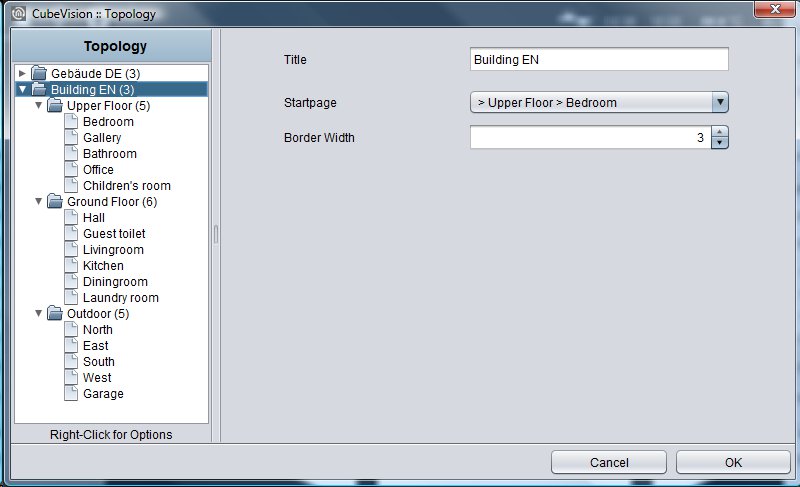
After appending the building, the right side of the configuration window shows corresponding options, as shown in figure below. These are:
-
The buildings name, which already has been entered before in “Insert a building”. This name can be altered in this field afterwards.
-
Front page. This option confirms, which window will be displayed, when CUBEVISION starts. In the pull-down menu, the entries will be shown in double figures. The rooms will be displayed after following scheme: > [level] > [room].
In case that the building will not be required anymore, it can be eliminated by the popup menu`s function „Delete building“. A right click has to be executed on the entry of the building, which should be erased.
Level
For appending levels to buildings, you have to use also the pop-up menu with its function „Append levels“
The pop-up menu has to be opened over the building, to add a level to this building. Like the procedure in creating a new building, a window will open here, in which the name of the level has to be entered.
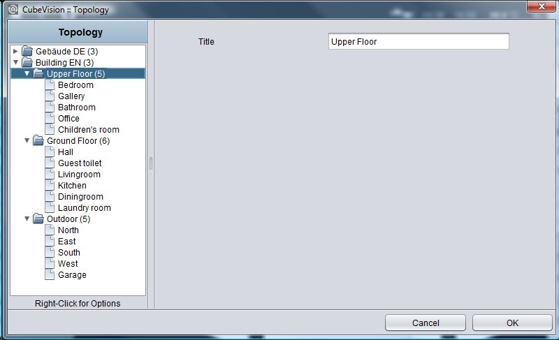
If the level is appended, the right side of the configuration window shows the attendant options (figure)
The level`s name. The name of the level was entered already by the creating of the level. But it can be altered in this field afterwards.
-
The Name of levels will be used in Quick Navigation. Every line of pictures in this view will be indicated with these names (see also figure).
If a level should be erased, this will happen by the pop-up menu`s function „Delete a level“. A right click has to be executed on the level`s entry, which should be deleted.
Room
By the same procedure as in buildings and levels, rooms will be added. An input window opens with the function “append a room”, in which the room`s name has to be filled in. The configuration window at the right side displays respective options. Possible options and configurations are the following (see figure below):
-
The rooms name.
The name of a room was entered by its creating already, but in this field, it can be changed afterwards.
The name of levels will be used also in Quick Navigation and in ICP. Every picture (background image), which was assigned to the room, will be indicated with these names. -
Background image.
To every room a background image will be assigned. It fills out a complete face of the cube. (which illustrates a room) The image can be elected in the pull-down menu or by a selection dialogue. This image will also be displayed in Quick Navigation, combined with its name. -
List of operating elements.
Below these two fields, a list of operating elements is situated. Three switches belong to this list.-
Minimize all. Folding in all operating elements, which are located in the list.
-
Maximize all. Folding out all operating elements of the list.
-
Operating elements can be fold out or fold in, for getting a better overview or for controlling all group addresses. The elements could also be fold out or fold in separately.
Add.
If an operating element will be appended, a dialogue with a list of 13 different operating elements opens and at the same time, a text field for the identifier, too. The configuration of operating elements is described detailed in chapter 5.3.4.
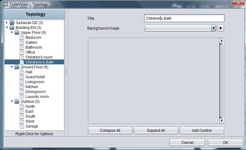
If a room should be erased, this will happen by the pop-up menu`s function „Delete a room“. The right click has to be executed on the room`s entry, which should be deleted
Operating elements
If an operating element should be appended, several possibilities are still available. So, the operating elements can be relocated in list or be deleted. Also, it will be convenient for proofing the sequence of the elements, to blank out the configuration of operating elements. In this case, only the headline with name und control element will be shown.
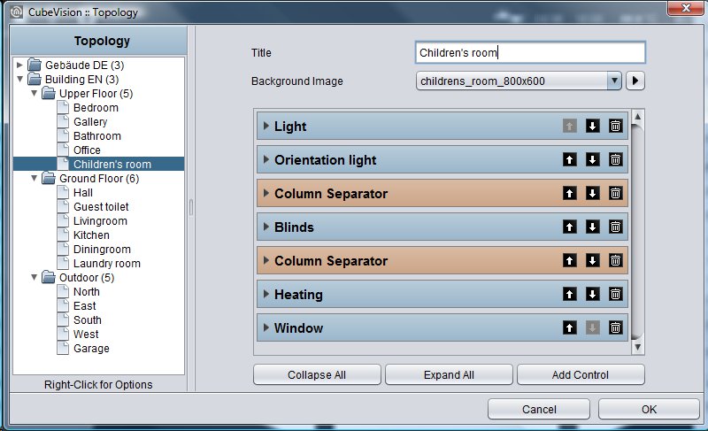
Figure below exposes the operating elements of the child`s room.
Header operating element.
All operating elements are folded in, so that you can only see the header of this element. On the left side, the name of operation element will be shown. On the right side, three buttons are located. Two of them will move this operating element up and down in the list. The third button will delete this element
Background image
The recommended resolution for the background image of the room depends on the size of the terminal device on which the visualization is to be displayed.
In general, the resolutions should be higher for larger terminal devices (PCs, 21" Touch Panel PC) than for small terminal devices (smartphone or tablet).
If all of the background images are of very high resolution, there are no problems for large screens; however, the waiting time might be slightly higher for small devices.
Room icon
The "Room Icon" selection determines the symbol that is presented in front of the name of the room in the room navigation in the CUBEVISION phone presentation. A certain number of symbols has already been loaded onto each device.
User administration
The access to the visualization is managed in the security settings.
Please protect your visualization with a strong and secure password if it is available via the Internet.
Switching to security settings
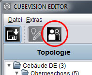
The security settings are opened using the corresponding button in the menu bar of the CUBEVISION Editor. In this menu, it is possible to switch between the "Visualization" and "Security Settings" menu items. Only the button that is selected in the view is marked at one time.
Settings
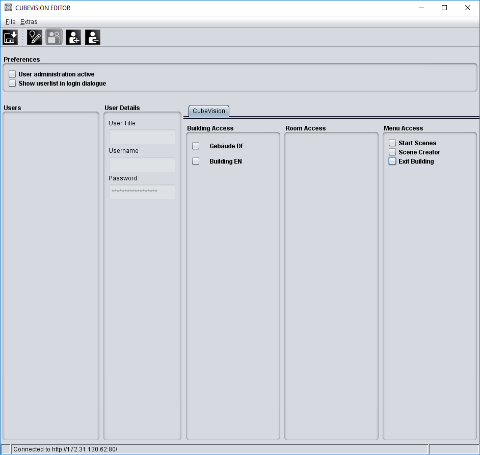
The user administration can be activated and deactivated. If the user administration has been deactivated, no user login is carried out.
-
With both "User Administration" and "Displaying User List in Login Dialog" deactivated, you can immediately access the projects (buildings).
-
With "User Administration" activated and "Displaying User List in Login Dialog" deactivated, the user must be entered.
-
With both "User Administration" and "Displaying User List in Login Dialog" activated, you can select the user from a user list and only have to enter the password.
Adding / deleting users
A new user is created via the corresponding symbol. As a first step, you must assign a unique name. This name is automatically taken over in the field "User Title" and "Username". As a second step, a password must be entered. In order to delete a user, you must first mark the respective user in the user overview.

The user is irrevocably deleted without any safety warning.
Permissions
Each user can individually be assigned the access rights to the projects (buildings) and visualization pages (rooms).
Granting access to buildings
Here, the projects (buildings) are shown. If a building is activated via the check box, the respective user is granted access to all rooms (visualization pages) of the building.
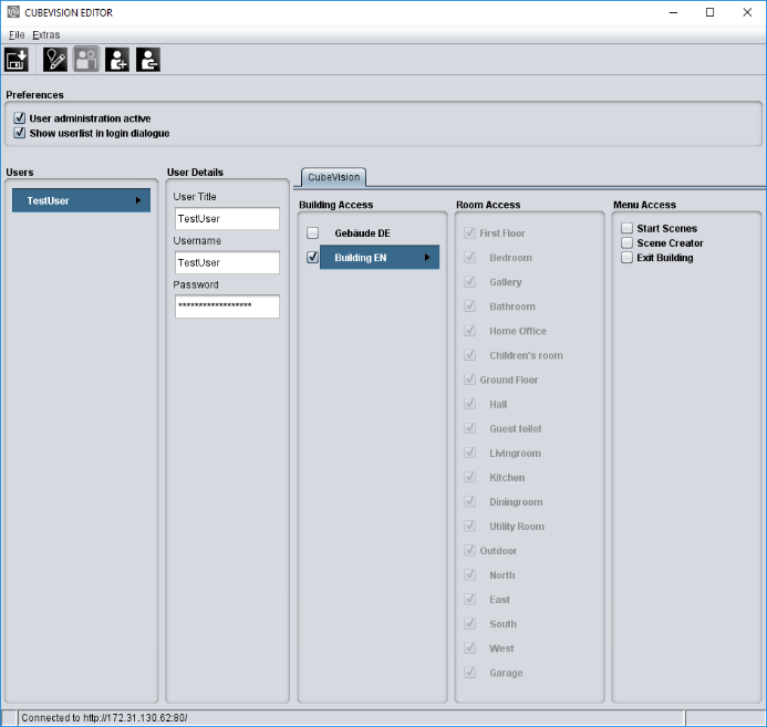
Granting access to rooms
Here, access to individual rooms or layers for the respective user can be granted. To do this, the check box in "Granting access to buildings" must not be set. It is thus possible to make your own authorization settings in "Granting access to rooms" for each room and layer via a check box.
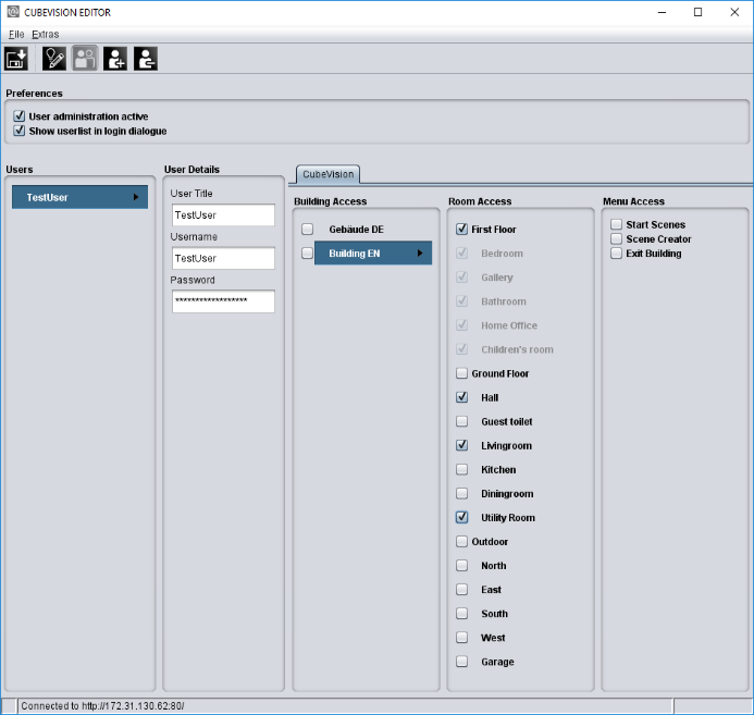
Menu Access
-
Start Scenes: Here you can specify whether a user is allowed to trigger the scenes that have been configured in Scene Creator.
-
Scene Creator: Here you can define whether a user is allowed to use the "Scene Creator". If the function is deactivated, the Scene Creator is not displayed for this user in the CUBEVISION.
-
Exit Building: If this function is deactivated, the user cannot leave the building/project.
These functions are disabled as default.
Saving the settings
The security settings are saved with the CUBEVISION configuration data using the "Save" button in the CUBEVISION Editor (see chapter "Saving the configuration").
Saving the configuration
A little tip: After the visualization project (building) has been created, it is sufficient to save the change by clicking the "Save" symbol (see figure below, orange circle). The changes are thus written into the CUBEVISIONMODULE! While working with CUBEVISION Editor, it is recommended to open a browser with the visualization in parallel in order to check and control the view of the visualization. If a new room, layer or control element is added, the changes are confirmed by clicking "Save". In the web browser, simply press the"F5" (updating) key once in order to make the change visible.