2 Assembly
The operating voltage of the APP MODULE is 12-32 V DC
The device shown here is the APPMODULE KNX (form factor identical for all models), REG housing 4 TE. Dimensions (width x height x depth): 70 x 90 x 63 mm
In order to ensure easy connection of the power supply, remove the screw plug-in terminals (see figure below).
Now connect the power supply cables to the respective screw plug-in terminals (see figure below). Please consider the polarity!
Now, you can re-plug the screw plug-in terminals into the APPMODULE.
In the next step, snap the device onto the mounting rail according to DIN EN 60715.
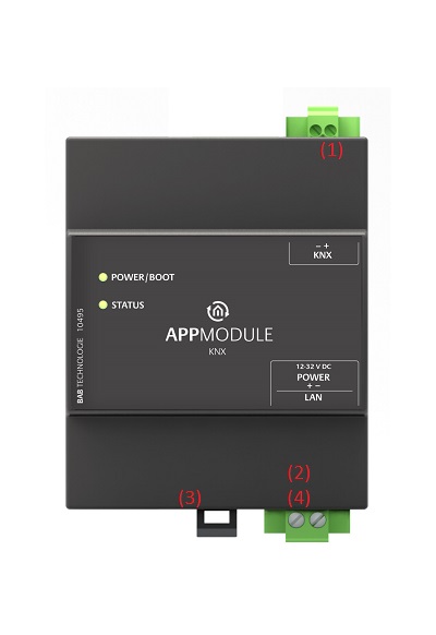
Figure 3: APPMODULE connection diagram
APPMODULE features
(1) | KNX connection (type 10495) via screw plug-in terminal |
(2) | Power supply via screw plug-in terminal 12-32V DC |
(3) | USB connection (is not activated) |
(4) | RJ-45 female connector for Ethernet LAN |
LED status
The APPMODULE has two DUO LEDs ("Power/Boot" and "Status"). Each DUO LED has a green and a red LED.
POWER / BOOT LED
LED display | Status |
OFF | The device is not ready for operation. No operating voltage is supplied. |
GREEN | The device is ready for operation. |
FLASHING ORANGE | The device is booting. |
STATUS LED
LED display | Status |
OFF | The device is booting. |
FLASHING GREEN | The device has been started; the LED simulates a "heartbeat". The flashing interval increases depending on the device utilisation. |
FLASHING RED | Communication takes place via KNX. |
Explanation:
The green "Power/Boot" LED lights up as soon as the APPMODULE is supplied with power. Two to three seconds after the power supply has been switched on, this LED also starts to flash red (flashing orange) until the booting process has been completed. Then the LED is permanently illuminated green, while the "Status" LED flashes green (simulates a "heartbeat"). The flashing frequency increases depending on the device utilisation.
It takes approx. 2 minutes to start the APPMODULE.
Initial Operation
If the APPMODULE has been mounted and started as described in chapter "Assembly", commissioning can now be continued as specified below.
Factory setting on delivery:
IP address | 192.168.1.224 |
Subnet mask | 255.255.255.0 |
Username | admin |
Password | admin |
Device Name | APPMODULE |
The password must be changed immediately when logging in for the first time. If the password is lost, the device cannot be reset!
Language
Web interface
The language used for the APPMODULE Web interface is based on the language set in the browser. German and English are currently available in the APPMODULE. If the browser is set to a language other than German or English, English is displayed in the APPMODULE interface.
Java application (EnOcean Editor)
The language in the “EnOcean Editor” Java-based application adjusts to the language set in the browser after start-up from the browser. If the app is used in BAB STARTER, the language set in the operation system applies. English is used if a language other than German or English is set.
System requirements
Current browser (e.g. Mozilla Firefox, Google Chrome, Microsoft Edge, Safari etc.)
If applicable, an app from the APPMARKET (https://www.bab-appmarket.de/de/ )
For EnOcean configuration: BAB STARTER or current JVM & JVM browser plugin
Establishing connections
In order to configure the APPMODULE, a current browser and a network connection to the device are required. If the device is in the condition of delivery, it can be accessed at the above-mentioned IP address and the network settings must be adjusted to the address range, where necessary. Please follow the information given in the chapter "Adjusting the network settings of your computer" for this purpose.
Call APPMODULE web interface with IP Adress or Host name
The APPMODULE is configured via its web interface so that it can be configured via each web browser. The "EnOcean Editor" layers are Java applications and also require a Java Virtual Machine (JVM) or the BAB STARTER (see "Establishing connections").
In order to call up the web interface, please proceed as described below:
Open a browser and enter the IP address or the Host name of the APPMODULE into the address line (Information about the factory settings can be found in chapter "Initial Operation")
Tip: Besides calling the APPMODULE web interface via the IP address, the web interface can also be called via a host name.
To do this, enter the assigned “APPMODULE” device name in the address line of the web browser,
followed by " .local ".
Example: The device name on delivery is "APPMODULE". Thus, the web interface of the APPMODULE can also be called as follows instead of the IP address:
appmodule.local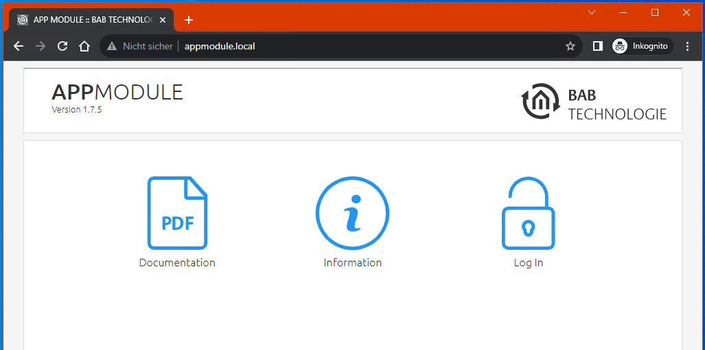
Figure 4: APPMODULE start page
You will reach the APPMODULE start page. The “Login” unlocks the “Configuration” Functions whereas “Information” shows general system information.
Use the user data to log in to the web interface: "Log In". (Information on the authorisation settings can be found in chapter "Initial Operation")
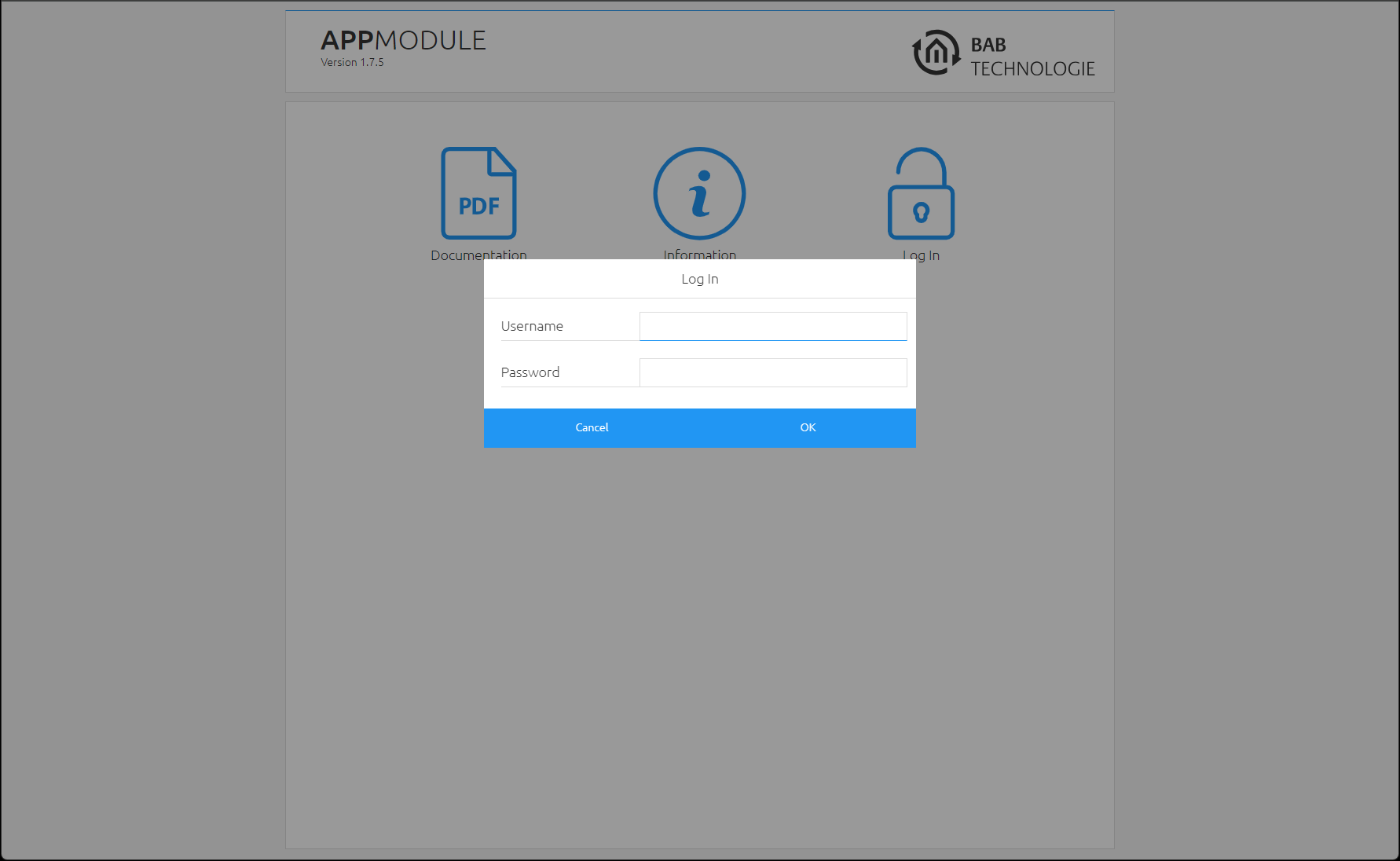
Figure 5: Logging in to the web interface
You can then also access the "Configuration" menu item. See chapter "Configuration"
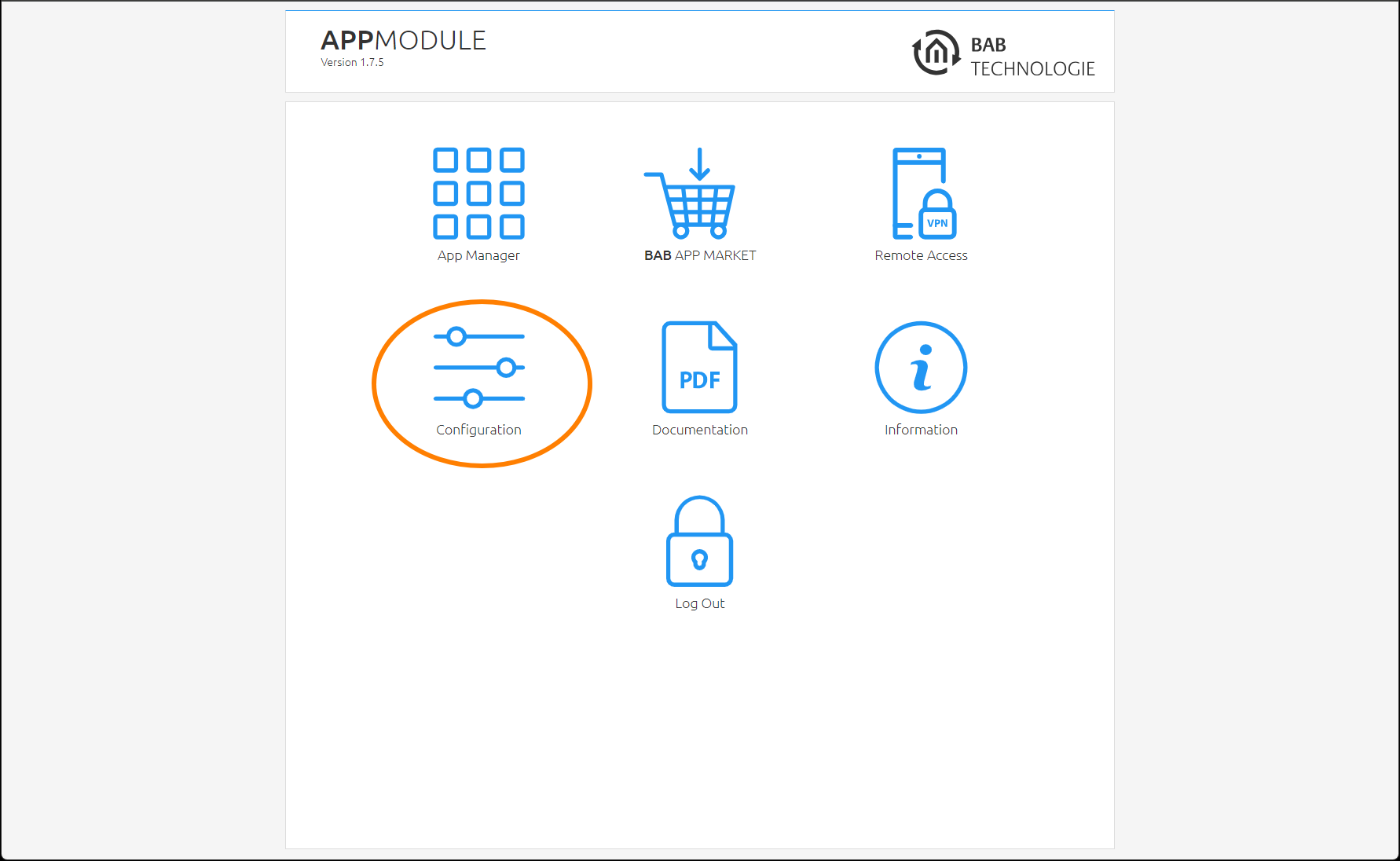
Figure 6: "Configuration" menu item
To return to the main menu, just click on “Start” or on the product name.
Figure 7: Back to the homepage
Adjusting the network settings of your computer
In order to adjust the network settings of your computer and establish a connection to the device, please proceed as described below:
Open the IP address settings (under Windows 11):
Click "Start Button" → "Settings"
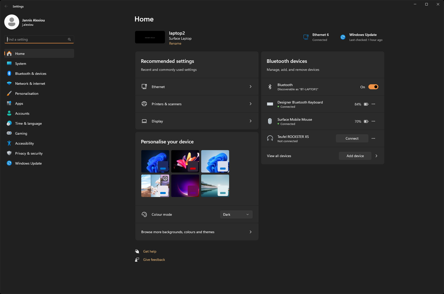
Switch to the → "Network and Internet" section
-20240426-095444.png?inst-v=05195b2c-e211-48ec-8de3-e4e7a25f429f)
Select the network interface used from the list. Here in the example "Ethernet".
-20240426-095445.png?inst-v=05195b2c-e211-48ec-8de3-e4e7a25f429f)
Next, click on "Edit" for the IP assignment of the Ethernet interface:
Make a note of the current configuration or create a screen copy so that this configuration can be restored later.
Select the "Manual" entry in the drop-down list and switch on the processing for IPv4.
Now change the IP address settings (IP address and subnet mask are sufficient) to switch to the IP address range of the APPMODULE.
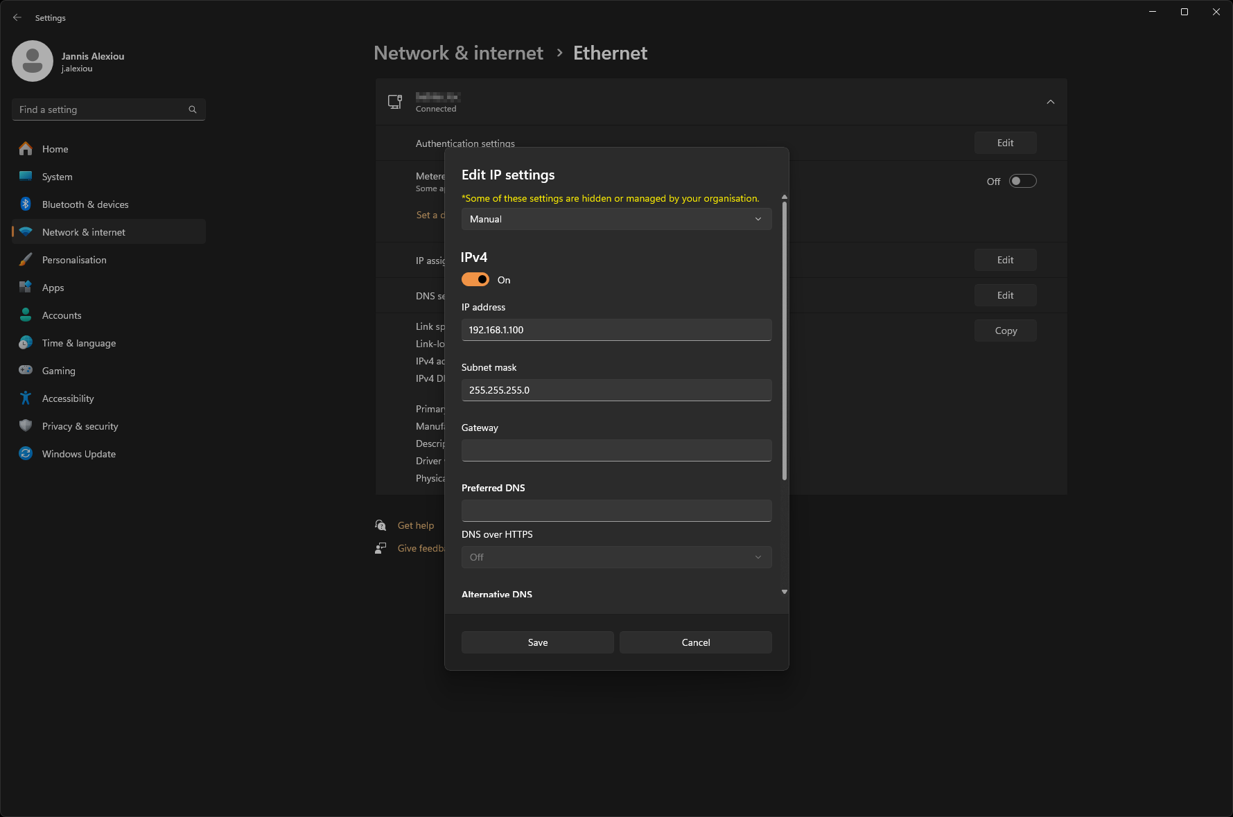
Example of a valid configuration for the factory settings of the APPMODULE:
Free IP address: 192.168.1.228
Subnet mask: 255.255.255.0
Now confirm your input with "OK".
Thus, you have adjusted the network settings of your PC to those of the CUBEVISIONMODULE X. The web interface of the APPMODULE can now be accessed by means of the browser. Please follow the instructions below to adjust the IP address setting of the device.
After the network setting for the APPMODULE has been adjusted, the network setting of the PC can be reset to the previous state in order to continue with the setup of the APPMODULE.
Adjusting the network settings of the APPMODULE
If the network prerequisites have been created, you can now access the configuration of the APPMODULE in order to adjust the network settings to the local requirements there. To do this, please proceed as described below:
Enter the IP address of the APPMODULE in the address line of your browser (for factory settings: 192.168.1.229).
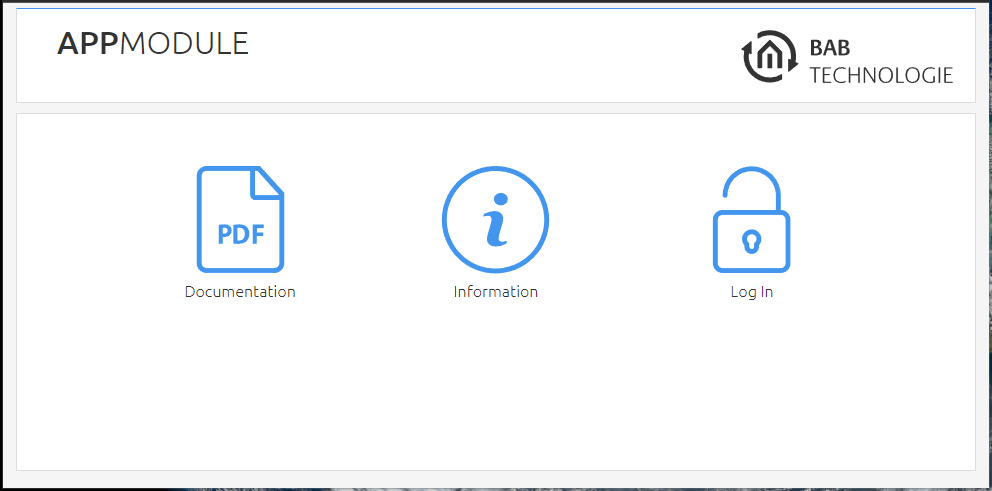
Figure 12: APPMODULE Webinterface
The start page of the APPMODULE opens up. Click "Log In".
A login dialog appears. For factory settings, the login data is as follows:
Username: | admin |
Password: | admin |
Figure 13: Login dialog
The password must be changed immediately when logging in for the first time. If the password is lost, the device cannot be reset!
Logging in only works if the browser is authorised to save cookies!
The view on the start page changes. You can now access the following levels:
App Manager
Configuration
Information
Log Out
In order to change the IP address of the APPMODULE, please click "Configuration"
Figure 14: APPMODULE – Main Menu
The configuration menu opens up. You can make the following settings in the "Network" menu item:
DHCP: | If the DHCP service is enabled, the device will automatically obtain the network settings. The DCHP service assigns the IP address, the network mask and the default gateway to the APPMODULE. Therefore, a DHCP server, in private networks mostly the router, must be available in the local network. If the DHCP service fails, the APPMODULE gets that with and is then reachable under the default IP address, network mask and standard gateway. |
IP address / subnet mask / gateway: | Field for the static assignment of IP addresses. Please make also sure that the subnet mask (often 255.255.255.0) and the gateway entry are correct. (Often the IP address of the WLAN router). Without a correct gateway entry, the device will not be able to communicate with the Internet. |
DNS server: | DNS is the abbreviation for Domain Name System. The DNS server converts Internet addresses, for example "http://www.bab-tec.de " into the IP address "85.214.89.170" and vice versa. Without a valid DNS entry, NTP-, weather- or UPnP services do not work. |
NTP server: | NTP is a free service for synchronising the system time of Internet-compatible devices. If it is not possible to establish the connection to an NTP-Server, the system time must always be checked and adjusted manually (see menu "General") NTP-Server list: e.g. http://www.pool.ntp.org/zone/europe |
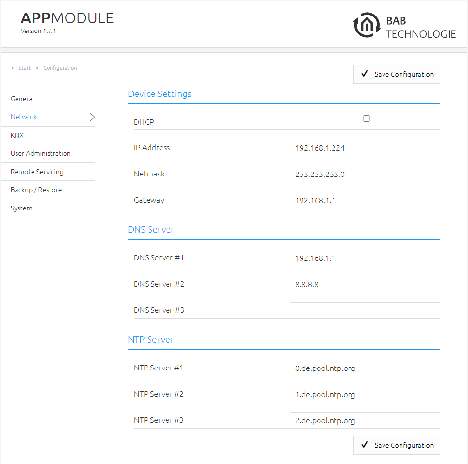
Figure 15: APPMODULE Network configuration
Change the IP address settings as required. In order to save the settings made, click "Save Configuration". The server in the device is restarted, the browser automatically connects to the new IP address if possible.
Please bear in mind that you might have to reset the IP address of your computer to the initial value in order to be able to access the APPMODULE after the change has been made.
Specialty when activating DHCP
If you have activated DHCP for the APPMODULE according to the steps mentioned above, please use the BAB STARTER like depicted in the chapter “Network” to find out the current IP-address.
///