
The LOGIKMODULE is designed as a DIN rail device with a width of 4 modules. The form factor is identical for all device versions.
-
Operating voltage: 12–32 V DC
-
Dimensions (W × H × D): 70 × 90 × 63 mm
-
Mounting: DIN rail according to DIN EN 60715
The connection diagram shown illustrates the LOGIKMODULE KNX.
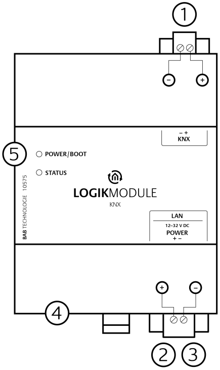
Connections
(1) KNX Connection
Only available on the KNX version (type 10575), connected via a pluggable screw terminal
(2) Power Supply
12–32 V DC, connected via a pluggable screw terminal
(3) Ethernet LAN
RJ45 socket for the network connection
(4) USB Port
Not used
(5) LED Indicators
Power/Boot LED and Status LED
Mounting and Connecting the Device
Proceed as follows to mount and connect the LOGIKMODULE:
-
Remove the pluggable screw terminals from the device to make it easier to connect the wires.
-
Connect the power supply wires to the corresponding pluggable screw terminal.
-
For the KNX version, also connect the KNX cable to the designated pluggable screw terminal.
-
Reinsert the pluggable screw terminals into the corresponding device connections.
-
Mount the LOGIKMODULE on a DIN rail according to DIN EN 60715.
-
Connect the network cable to the RJ45 socket.
-
Switch on the supply voltage.
-
Then check the LED status of the device (see chapter “LED Status”).
Note
The operating voltage of the LOGIKMODULE is 12–32 V DC. When connecting the power supply, always observe the polarity indicated on the front of the housing.///
///