
The LOGIKEDITOR is launched via the BAB STARTER or the web interface of the respective device. To do this, open the device interface in a supported web browser and select the LOGIKEDITOR.
For information on initial commissioning, network configuration, login, and user management, refer to the manual of the respective product.
Note
Access to the LOGIKEDITOR may vary depending on the product and firmware version. Refer to the respective product manual for details.
User Authentication
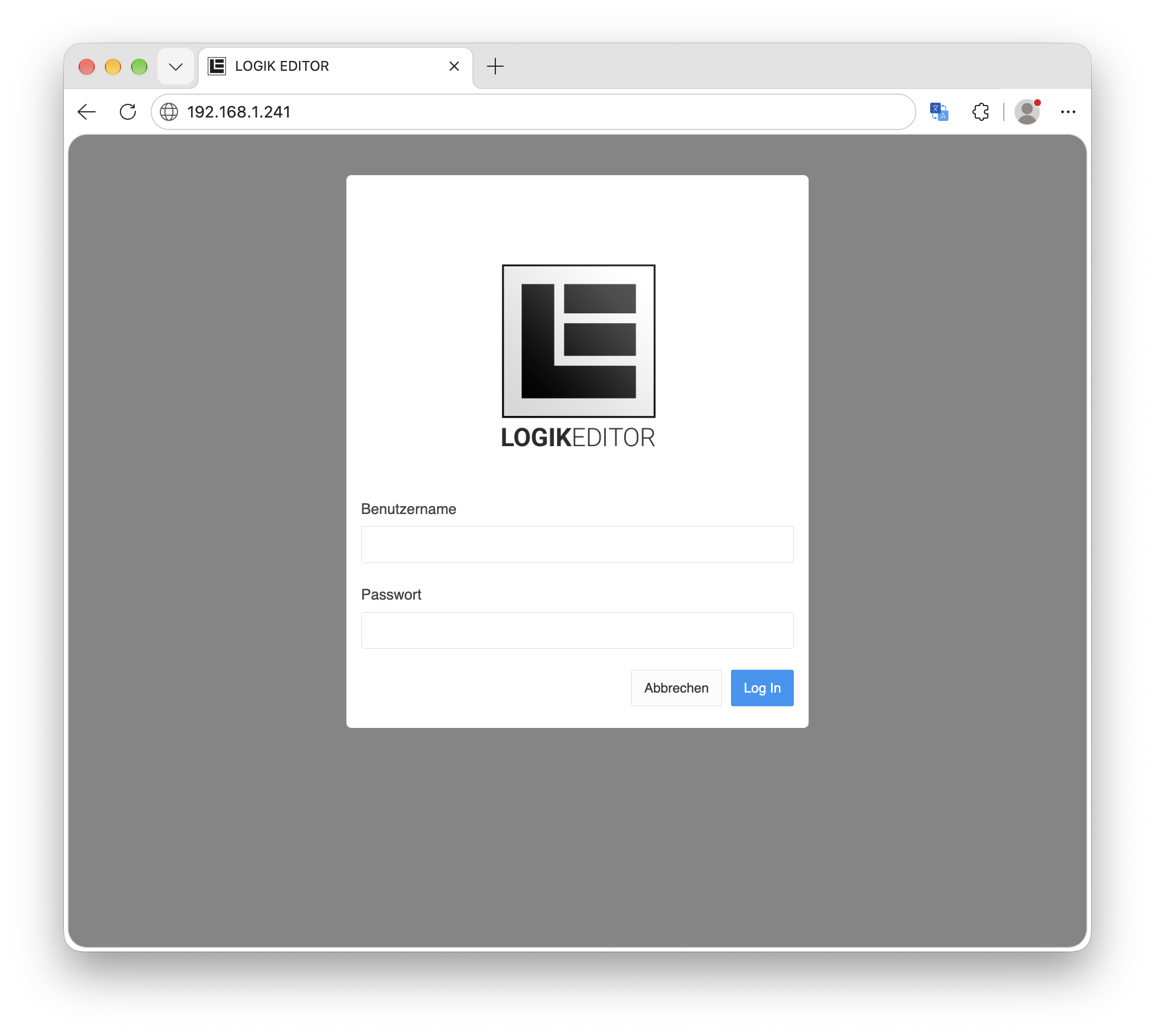
Log in using the user credentials configured on the respective device.
For more information on user management and login, refer to the manual of the respective product.
Logic Groups
In order to obtain a canvas allowing for creating the graphic links with inputs and outputs, a new logic group must be created.

Functional Modules
Within logic groups, there are three possible types of functional modules:
-
Tools (simple operators)
Connection to the system / data points
The connection to the installation and to other functional areas of the respective device is established by configuring the inputs and outputs.
Depending on the data point used, the input and output objects provide the corresponding connection points.
For more information on linking and configuring data points, refer to the Datapoints chapter.

Currently, LOGIKEDITOR supports KNX. Further bus systems will be added in the following expansion stages (e.g. EnOcean, Rest-API, Modbus, MQTT etc.). Information on how to load a KNX project can be found in chapter KNX Projectdata (ETS) import.
Internal Links
In order to link the functional modules (value input, value output, logic elements, tools) to one another, it is sufficient to draw lines between the tie points. See chapter Internal Links for additional information.
Logic Elements & Tools
Along with logic elements, providing a very comprehensive scope of functions, there additionally are so-called "tools", with the help of which simple actions can be implemented within the links between two functional modules. A description of the existing logic elements can be found in the chapter Logikelements, and a description of the tools can be found in chapterTools .
-
Add Logic Elements:

-
Add Tools:

Working Copies
LOGIKEDITOR works with "working copies". During configuration, a working copy is automatically opened in the browser, which can then be edited there but does not have any influence on current operations. The settings can be simulated in the working copy. In order to activate the modified configuration for the system, the working copy must be transferred to the device using "Activate". See chapter Logic Groups - The LOGIK EDITOR Canvas.
Simulation Mode
LOGIKEDITOR has a simulation mode that can be used to set any start time and time scaling. See chapter Logic Groups - The LOGIK EDITOR Canvas.
Keyboard Commands
In addition to mouse and touch control, the LOGIKEDITOR also supports keyboard commands. Besides a number of generally available shortcuts, there are some that only work on certain pages. You can get an overview of the supported commands on any page by pressing the '?' key, or clicking on the question mark symbol in the right area of the top bar.
///