
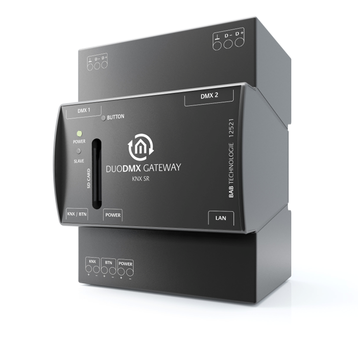
The REG version of the DUODMX GATEWAY is designed for DIN rail mounting in accordance with DIN EN 60715.
Enclosure
-
DIN rail enclosure, 4 TE (4 module units)
-
Dimensions (W × H × D): 70 × 90 × 63 mm
DIN Rail Installation
The pluggable screw terminals for the power supply and the DMX bus are removable to simplify wiring (see figure).
Connect the power supply and the DMX bus wiring to the corresponding pluggable screw terminals. Ensure that the correct polarity is observed.
After wiring, reconnect the pluggable screw terminals to the DUODMX GATEWAY.
Finally, snap the device onto a DIN rail according to DIN EN 60715.
Connection Overview
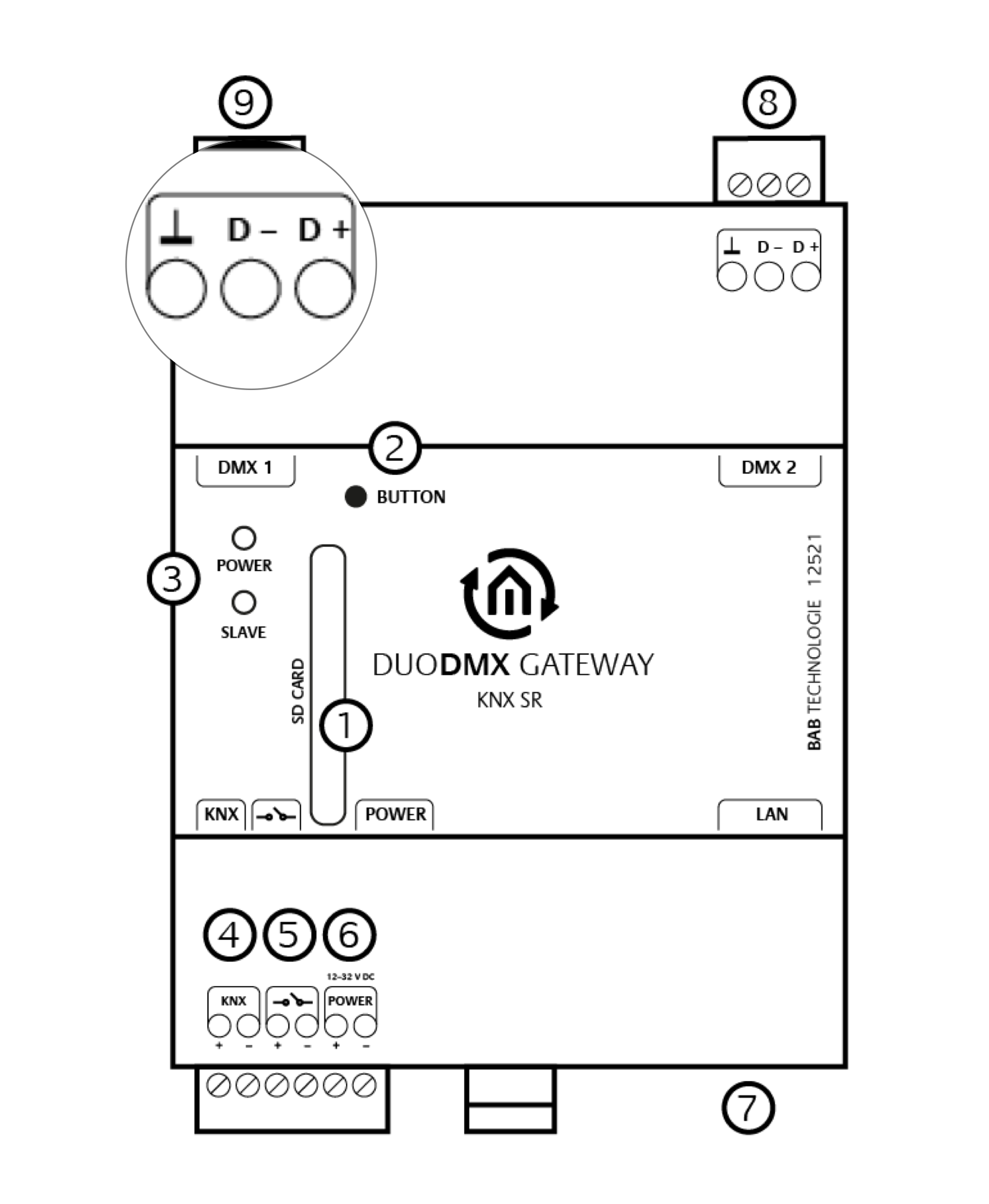
The following figure provides an overview of the connections of the DUODMX GATEWAY REG version.
DMX Bus Connection
The device features two independent DMX interfaces. Depending on the device configuration, each interface can be configured to operate as either a DMX Master (transmitting) or a DMX Slave (receiving).
The connection is made using two 3-pin pluggable screw terminals. The polarity is marked on the device housing.
It is also possible to use only one DMX interface. For SR device variants, the DMX interfaces are short-circuit protected.
|
Pos. |
Description |
|---|---|
|
1 |
SD card slot |
|
2 |
Push button |
|
3 |
LEDs |
|
4 |
KNX/TP connection |
|
5 |
Potential-free push-button input |
|
6 |
Power supply |
|
7 |
Ethernet connection |
|
8 |
DMX Interface 2 |
|
9 |
DMX Interface 1 |
A description of the DMX connector pin assignment for DMX plugs and sockets can be found at the end of this document.
-
Always ensure the correct polarity when connecting the power supply.
-
The polarity is marked on the device housing.
-
Do not interchange the pluggable screw terminals for the power supply and the DMX connections.
///