
Contents
KNX Data Points
To link value inputs and value outputs within logic groups to KNX data points, the corresponding data points must first be created and configured.
The KNX data points establish the connection between the LOGIKEDITOR and the KNX installation.
Data points are managed under System > Data Points.
The following sources can be used to create KNX data points:
-
ETS project data
-
ESF files
-
manually created data points
Note
On EIBPORT and FACILITYMASTER EIBPORT, the configured KNX data points can also be used in other functional areas of the device, for example in visualizations or jobs.
The available functional areas may vary depending on the firmware version in use.
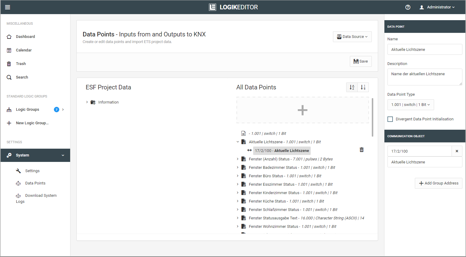
Creating Data Points
There are three ways to create a data point:
-
Double-click a group address in the KNX project tree on the left.
-
Drag and drop a group address from the KNX project tree to the right-hand side:
-
onto the gray area with the plus sign (+) above the right-hand tree
-
between two existing data points in the right-hand tree
-
-
Click the “+” gray area above the right-hand tree. This allows you to create a data point without reference to a KNX project file.
The first two options create data points that are linked to the KNX project.
Extend
Every data point can contain one sending / listening object and up to 19 listening objects: There are two ways to extend a data point:
-
Drag and drop from the left-hand tree to an existing data point.
(In this case the data point type has to match which is ensured by an automatic filter.) -
In the data point configuration (right-hand column) via the “Add Group Address” button
Configuration
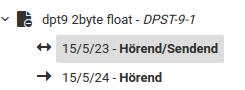
In the tree view of the data points, the top group address is always listening and sending, and the subsequent ones are only listening. The total number of group addresses per data point is limited to 20. The order can be changed via drag and drop.
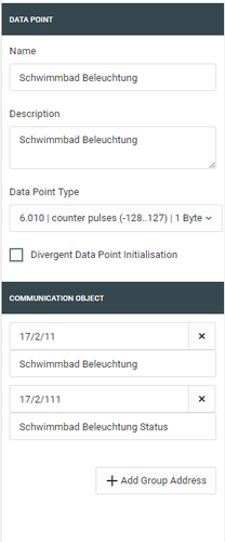
In addition to the name and description of the data point, you can also configure the data point type and group addresses together with the individual description. These changes may then differ from the information status in the KNX set-up software ETS.
With data points which have not been created in a KNX project (i.e. manually by clicking on the grey surface), the data point type can also be changed at a later moment in time.
Important
If you change the type of a data point, it will also have an effect on the inputs and outputs of the logic groups in which it is used.
Available data point types
A listing of the data types available in the LOGIKEDITOR is available here. If the data types have not yet been connected in the KNX set-up software ETS, or if a requested data point type is not implemented in the LOGIKEDITOR, with certain data types, via the “individual value range” function, you are given the option to configure the value range as required (see the following section).
Individual value range
To be able to depict the individual value ranges, you are able to change the factor, offset, minimum and maximum value of the data point. This selection is available to you with the numerical DPT main types (e.g. DPT 9.*). It is not possible, for example, to occupy DPT 3.* (Dimming), DPT 232.* (RGB) or DPT 16.* (Text) with an individual value range.
One example of use would be the use of DPT 9.* (two bytes floating point value) as DPT 9.004 (Lux 0 - 670.760). In such cases you can simply set the minimum value to 0.
Calculation
From the bus in the direction of LOGIKEDITOR, the input value
-
is multiplied with the factor.
-
is added with the offset.
-
is checked for falling short of the minimum value.
-
is checked for exceeding the maximum value.
The value determined in this way is transferred to the logic groups via the value input.
From the LOGIKEDITOR in the direction of the bus, the output value
-
is checked for exceeding the maximum value.
-
is checked for falling short of the minimum value.
-
is subtracted with the offset.
-
is divided by the factor.
The value determined in this way is converted into a bus telegram. The corresponding limits of the main type apply here.
Initialization
In addition to the settings for all data points, you are also able to equip a data point with individual initialisation settings. The configuration is described here under data point initialisation.
///