When mounting the device and during the initial operation please take care and note the following information to prevent any risk.
Attention!
Device may be destroyed in case of wrong use. Operations under voltage may cause residual voltage. Before connecting the device, please disconnect the installation environment from voltage.
Please pay attention, that EIBPORT is protected against polarity reversal, but not against surge voltage. In case excessive voltage will be connected, EIBPORT can be destroyed.
General
|
Environmental requirements |
|
|---|---|
|
Voltage:Voltage: |
12 - 30V |
|
Power Consumption: |
<= 4 W |
|
Climate persistent: |
accordance to EN 50090-2-2 |
|
Ambient temperature: |
0 - 45 °C |
|
Rel. humidity (not condensing): |
5 % - 80 % |
Plugging the device
Snap the device onto the top-hat rail accordance to 60715.
Power supply
When establishing the power supply, please make sure that sufficient power is available. The EIBPORT requires 300 mA at 12 V during the boot process. Connect the power supply unit according to the marking on the screw-type terminals (figure 2 (1)).
Ethernet
For programming the EIBPORT it is necessary to access via LAN. This can be done both using an existing LAN network or via direct connection. Plug in the network cable (LAN) into the RJ 45- connector (Figure 2(4)).
Prerequisites of the Client PC
To use EIBPORT a PC with network adapter is necessary. An UpToDate browser as well as an actual Java environment should be part of the operating system.
Note: If the browser blocks the execution of Java, please use the BAB STARTER.
ETS
The EIBPORT does not require an ETS application. The BCU does not need to be programmed. Please also refer to chapter "Physical address".
The device warms up during operation. Take care about the maximum ambient temperature and for sufficient thermal discharge.
Additional information for KNX
To establish optimum operating conditions and performance the EIBPORT should be connected to the KNX bus system. It is of prior importance that the device is supplied with bus voltage; real devices on the bus system are not needed.
Plugging the device
-
Connect the bus wire with the bus clamp (figure 2, (8))
-
Switch on the bus voltage
Additional information for EnOcean
Plugging the device
Screw the SMA plug on the SMA connector to tighten it (fi.
Additional information for 1-Wire
Connecting the device
In most cases 1-Wire devices are powered via USB (1-Wire bus master). If the 1-Wire sensors are to be operated as slaves, i.e., without their own power supply, 15-20 slaves can be coupled using a 1-Wire adapter/bus coupler, with a line length of approx. 20-30 metres.
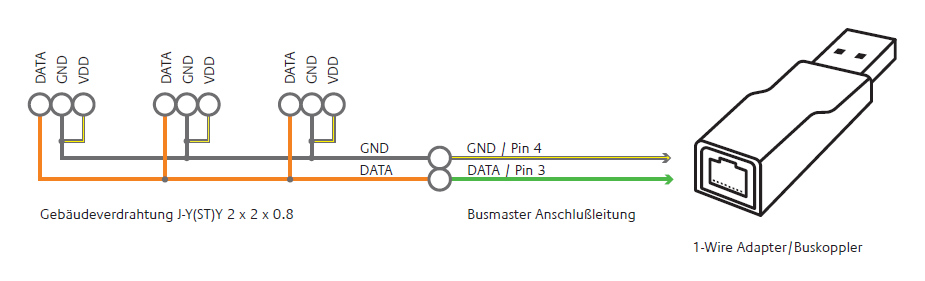
Connect the 1-Wire adapter to the EIBPORT 's USB port The 1-Wire network is connected to the EIBPORT via the 1-Wire USB adapter.
Additional information for LTE
The SIM card is not assembled by default and can be selected and changed freely by the customer.
Initial commissioning, as well as the change of SIM card will be described in the additional instruction “EIBPORT LTE initial operation”.
Technical data LTE Module:
-
Quad Band GSM Modem (850/ 900/ 1800/ 1900 MHz)
-
SMS sending and receiving.
Requirements of the SIM-card:
-
Provider: Provider must ensure a good signal at the mounting location.
-
Tariff: Because EIBPORT will send and receive SMS, the tariff should offer cost advantages according to that. To do a first test with the SIM-card after mounting, “Roaming” should be enabled (in case the provider is located outside of Germany).
-
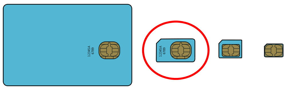
Size of SIM-card: For EIBPORT the SIM- card size “Min” is needed (see figure below, red circled). Here is an overview of all SIM-cards sizes:
ADDITIONAL FOR S0
-
Connect 24 V DC to the terminal for the S0 pulse input power supply (Figure 6 (5)). No 230V!
-
Connect S0 pulse input devices to the S0 pulse input terminals as follows (Figure 6 (4)).
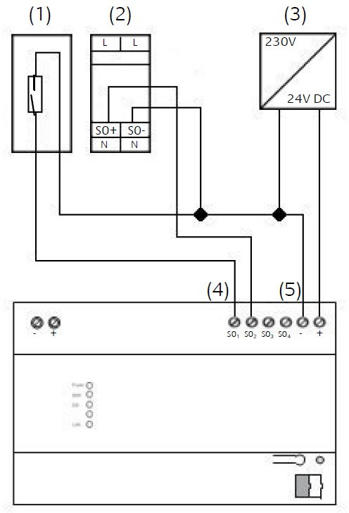
(1) Reed-contact to be placed on the counter.
(2) e.g., ELTAKO Single-phase Energy Meter WSZ12D-32A
(3) Power Supply 24V DC
(4) S0 pulse input terminal for analysing measured value
(5) Terminal for S0 pulse input Power Supply 24V DC
Operating State
When all connections are made correctly the device may be supplied with power. Please wait until the device has booted completely before checking the correct installation. The boot phase takes about 2 minutes. Have a look at signal LEDs (figure 1 (3)).
If everything is done correctly 3 LEDs are flashing
|
Power LED |
green |
|
BMX LED |
green |
|
EIB LED |
green (eventually blinking) |
|
LAN LED |
green (eventually blinking) |
-
If the EIB LED of the device is not lighting green, the KNX-driver of the EIBPORT is not started. Please reboot the EIBPORT.
-
Is the LAN LED not lighting, there is no LAN connection available. Please check the LAN cable resp. the connection.
-
If the Power LED is orange, the device is not started correctly.
-
Does not appear the BMX LED to be green; the Application Server is not started. If this doesn’t change even after several reboot try-outs, the device is defective.